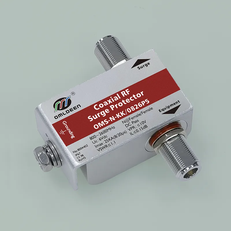
OMS-N-KK/0826P5, 0.8-2.6GHz, 25KA, DC Pass, 5V, GPS Antenna Lightning Protector, Antenna Surge Protector (Antenna Lightning Protector, Base Station Antenna Lightning Arrester), Bias Feed Type
Products::
OMRDON 0.8-2.6GHz composite antenna surge protector (lightning protection) is suitable for mobile communication frequency band transceiver system, so that it is protected from over-voltage damage such as induced lightning strikes and electrostatic discharges introduced by the antenna feeder. This product is waterproof and dustproof, and can be used in outdoor installation places. It is installed in lightning protection partition LPZ0A-1 and subsequent partitions.
The product adopts IP67 aluminum alloy shell package, built-in high-quality high-speed over-voltage protection devices, designed for the need to “remote power supply” RF system design (such as: active antenna, tower top amplifier, etc.), the residual voltage is very low, the antenna feeder induction of lightning high-voltage pulses with high efficiency of protection and defense function.
Functional Features::
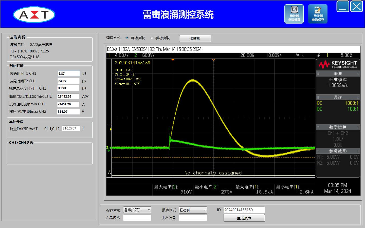
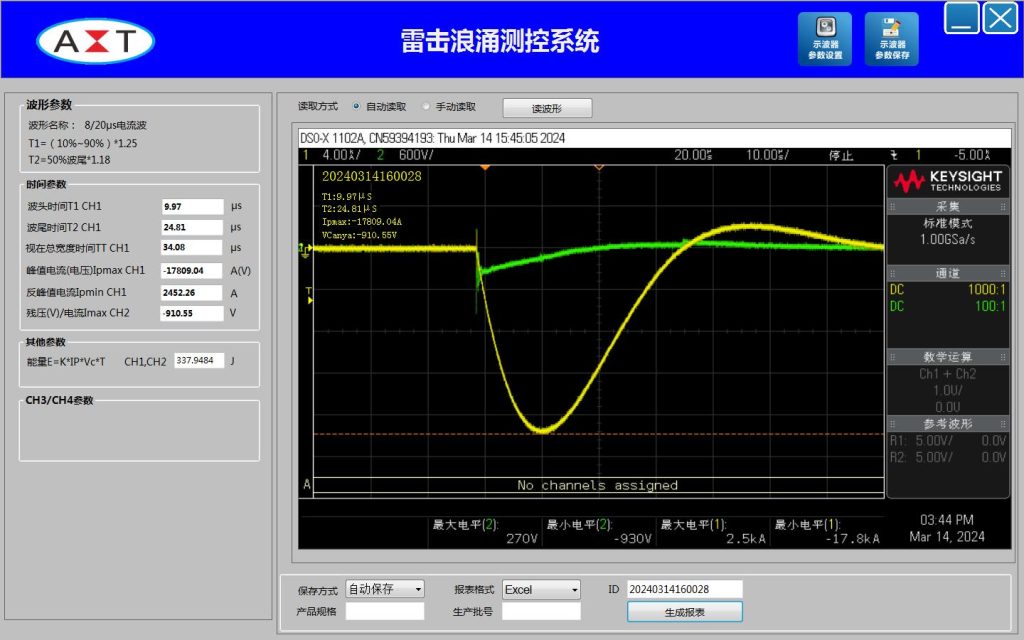
Lightning impulse current up to 25KA
Continuous output power ≤300W
Frequency range 0.8-2.6 GHz
Feedable (DC Pass)
N-type connector one male(female) to female (male(female) to female)
Very low VSWR <1.1
Characteristic impedance 50Ω
International Certification RoHS, CE, FCC
typical application::
satellite communications
GPS base station
PHS (PAS) base station
radar base station
microwave station
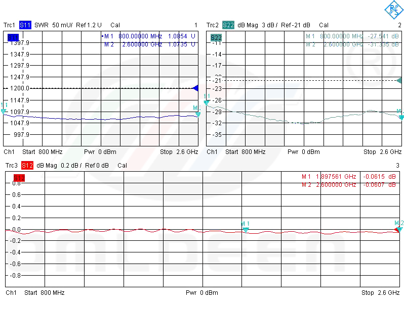
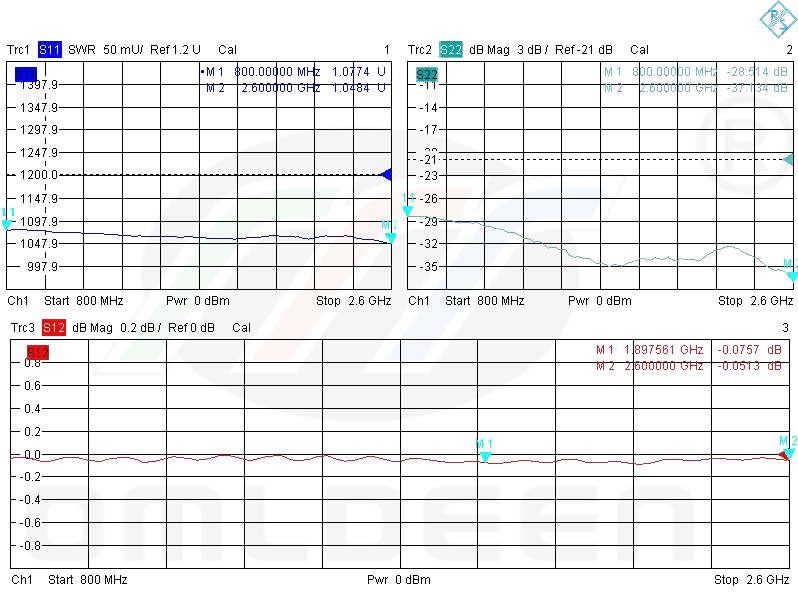
Technical Parameters
Electrical Specifications
model number
OMS-N-KK/0826P5 OMS-N-JK/0826P5
Rated operating voltage (Un)
5Vdc
Maximum continuous operating voltage (Uc)
6Vdc
rated current
DC4A
Nominal Inrush Current (In) (8/20μs)
20KA
Maximum inrush current (Imax) (8/20μs)
25KA
Response time (Ta)
≤25ns
Input power (CW)
300W
V.S.W.R
≤1.1
Voltage Protection Level (VPR) (8/20μs@20kA)
≤15V
Voltage Protection Level (VPR) (1.2/50μs@4kV)
≤10V
Residual energy (E) (8/20μs@3KA)
20μJ
(electrical) impedance
50 Ω
insertion loss
≤0.15 dB
frequency range
0.8-2.6 GHz
series impedance
0.5Ω±20%
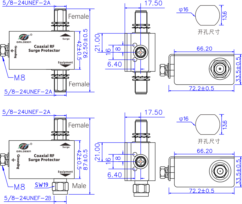
Mechanical specifications
interface method
N@K/K (J/K)
makings
Aluminum@Anodizing
Grounding resistance Ω
≤4Ω/≥4mm2
sizes
92*82*33.5mm
weights
278g [0.612 lbs]
Environmental norms
Operating Temperature Range
-40 ~ +85℃, altitude ≤4km
Relative air humidity
30%~90%
Protection class (IP)
IP67
Other information
Compliance Certification
CE, RoHs, FCC, IP67, ISO9001-2015
Implementation of standards
gb/t18802.21/lec61643-21
part numbers
8004402, 8004403
Product Series
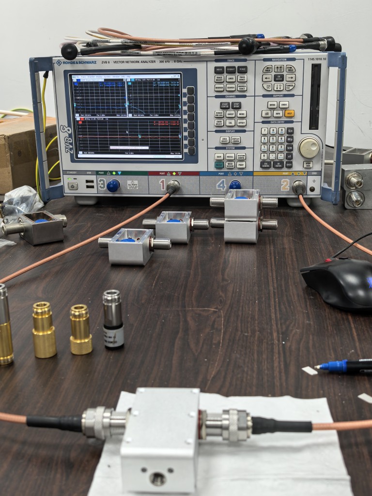
Typical Performance Test Data
Simulated Lightning Impact Test
Product Dimension Drawing
Installation Notes: 1. In order to reliably prevent the lightning attack, you can connect an antenna lightning protector in series at the output of the antenna and at the input of the protected equipment. Please note: The antenna lightning protector should be differentiated between input/output terminals, with the input terminal connected to the surge terminal and the output terminal connected to the protected equipment, please do not connect it in reverse, or it will result in a discounted protection effect. 2, the lightning protector on the grounding screw connection as short as possible on the grounding wire (wire area of not less than 4mm)2), the other end is reliably connected to the lightning protection system grounding bus, and the grounding resistance is not more than 4Ω. 3, the product has a waterproof function, but in the outdoor use of the antenna feeder should also pay attention to rain, do not let the rain soak into its internal corrosion damage. 4, this product does not require special maintenance. When the system works faulty, you can remove the lightning protector and then check, if the system returns to normal after restoring to the state before use, it means that the lightning protector has been damaged and must be replaced immediately.
Q1:What systems can this antenna feeder be used in? A: Applicable to all types of RF systems with an operating frequency band of 0.8-2.6GHz, including but not limited to:
BeiDou/GPS and other satellite positioning base stations
4G/5G Mobile Communication Base Stations
Satellite communications, microwave links
Radar, wireless video transmission system
Q2: Does the product support DC power (DC Pass)? A: Support. The standard model provides a 5V/4A DC feed path to remotely power an active antenna or tower amplifier. Also available in 24V, 36V, and 60V versions.
Q3: Do the insertion loss and VSWR of a lightning protector affect system performance? A: The product insertion loss ≤ 0.15dB, VSWR ≤ 1.1, in the vast majority of systems introduced by the impact of negligible, to ensure high quality signal transmission.
Q4: How to install and ground? A: It is recommended to install it at the antenna port close to the equipment, install it in series, and make sure that the enclosure is reliably grounded through a ≥4mm² wire (grounding resistance ≤4Ω is recommended). Please refer to the product manual or consult our sales or technical engineers for specific installation methods.
Q5: What does protection class IP67 mean? A: IP67 indicates that the product is completely dustproof (first digit “6”) and can be briefly immersed in water (second digit “7”), suitable for long-term outdoor use.
Q6:Is there any certification for the product? A: It has passed CE, RoHS, FCC and other certificates, and complies with IEC 61643-21, GB/T 18802.21 and other international and domestic lightning protection standards.
Q7: Are different connector interface models available? A: Provide a variety of combinations between N-type male (M), female (F): F/F, F/M, M/F, can be selected according to the actual link connection requirements. Customized production of other interfaces (e.g. DIN7/16, TNC, SMA) is also available.
Q8: Will the protector continue to work if lightning strikes? A: Products are designed toSelf-recovering after lightning strikeIf the maximum through-current capacity is exceeded, the internal protection circuit may be damaged and need to be replaced. If the maximum through-current capacity is exceeded, the internal protection circuit may be damaged and need to be replaced.
Q9: How can I tell if the protector has failed? A: A preliminary judgment can be made in the following ways:
Use a multimeter to measure the DC resistance of the inner conductors at both ends of the connector (abnormal open or short circuit);
Test the VSWR with a vector network analyzer (if significantly worse it may be damaged). Regular testing is recommended, especially after the thunderstorm season.
Q10: Is it possible to customize the product for other frequency bands or power? A: Yes. We support customization for different frequency bands (e.g. 689∼2700MHz, 800∼2500MHz, 1200∼2700MHz, etc.), higher power (e.g. 500W), please contact our sales team for customized solutions.
How to choose the right antenna lightning protector for a base station: a professional guide for engineers
In a base station system, the antenna feeder is the key channel connecting the antenna to the transceiver equipment, and it is also one of the paths most likely to introduce lightning surges. A single lightning strike can cause damage to equipment worth hundreds of thousands of dollars, resulting in long network interruptions. Therefore, choosing an appropriate antenna lightning protector (also known as surge protector) is crucial. This article will provide an in-depth analysis of the key technical parameters for selecting an antenna surge protector to help engineers make informed decisions.
I. Importance of antenna feeder in base station
Antenna feeder is not a simple “fuse”, but the base station lightning protection system of theFirst line of active defense. Its core roles include:
Protecting expensive equipment: Prevent lightning surges from damaging core equipment such as RRUs and BTS RF units through feeder lines
Maintaining network continuity: Reduce downtime of base stations due to lightning strikes to safeguard communication services
Reduced maintenance costs: Avoid frequent equipment replacement and on-site maintenance
Compliance with safety norms: Meet national lightning protection standards (e.g. GB 50689-2011) and operator acceptance requirements
Second, the choice of antenna feeder lightning arrester 9 key parameters
1. Frequency range: matching the operating frequency band of the base station
crux: The operating frequency band of the lightning protector must completely cover the operating frequency of the base station antenna.
Common Base Station Frequency Bands::
4G LTE: 700MHz-2700MHz
5G NR: 3300MHz-5000MHz (Sub-6GHz)
GPS/BeiDou: 1176MHz-1602MHz
suggestion: Select a lightning protector with a bandwidth slightly wider than the actual requirement, e.g. 0.8-2.7 GHz.
2. Impedance matching: ensuring signal integrity
standard value: The vast majority of base station systems utilize50Ωcharacteristic impedance
Consequences of mismatch::
Increased signal reflections leading to deterioration of VSWR
Reduced transmission efficiency and coverage
Indicator requirements: The impedance of the lightning protector shall be 50Ω±5%.
3. Power capacity: matching base station transmit power
The transmit power of communication base stations ranges from 4-10W for conventional macro stations to thousands of W for 5G millimeter wave, depending on the type of base station, frequency band and technical architecture.
formula::
BTS transmit power + tower gain ≤ maximum RF power of the lightning protector
Typical Base Station Power Rating::
Micro base station: 5-20W
Macro base station: 40-80 W (single carrier)
High power base station: 80-300W
safety margin: It is recommended to select a power capacity of 1.5-2 times the actual power.
4. Lightning protection level: adapted to the intensity of thunderstorms in the area
Surge current index::
8/20μs waveform: simulates induced lightning current waveforms
10/350μs waveform: simulates direct lightning current waveforms
Selection basis::
Area thunderstorm day rating
Recommended Inrush Current Capacity
Less mined areas (≤20 days)
10-15kA (8/20μs)
Medium minefield (20-40 days)
15-25kA (8/20μs)
Multi-mined areas (≥40 days)
25-40kA (8/20μs) with consideration of direct lightning protection
Strongly mined areas (high mountains, coasts)
40kA or more and consider direct lightning protection
5. Electrical properties: insertion loss and VSWR
insertion loss: Should be ≤0.2dB, high quality products up to ≤0.1dB
Voltage Standing Wave Ratio (VSWR): Should be ≤1.2, high quality products can be ≤1.1
test and verify: Require vendors to provide full-band S-parameter test reports
Optimal location: at the entrance of the antenna feeder into the server room (when only one lightning protector is installed at each end of the antenna and receiver)
Sub-optimal location: equipment outputs at the top of the tower (when only one lightning protector is installed at both the antenna and receiver ends)
Avoid location: long-term stagnant water place, direct sunlight place
Grounding requirements
Ground wire cross-sectional area ≥ 4mm² (copper core wire)
Ground resistance ≤4Ω (mountainous base station ≤10Ω)
Keep the ground wire as short as possible and avoid bending it
waterproofing
Seal both connector ports with waterproof tape or heat shrink tubing.
Make sure the waterproof rubber ring is intact
Drench test after installation
periodic testing
Recommended periodicity::
Before the thunderstorm season: comprehensive testing
Immediately after a lightning strike: testing
Routine maintenance: tested every 6 months
Testing Program::
Visual inspection (damage, corrosion)
Ground resistance measurement
VSWR Test
IV. Common Misconceptions and Answers
Myth 1: “Insertion loss is negligible”
reality: Losses accumulate when multiple lightning protectors are connected in series. In large MIMO systems, even 0.2 dB of loss may affect the coverage edge rate.
Myth #2: “Once installed, it's done.”
reality: Lightning protectors are consumables and their performance will gradually deteriorate after many lightning strikes, requiring regular testing and replacement.
Myth 3: “Price determines quality”
reality: Some low-priced products may be falsely labeled on key parameters (although third-party test reports are claimed). Suppliers should be required to provide actual test data reports.
V. Conclusion
Choosing the right antenna lightning protector requires comprehensive considerationTechnical parameters, environmental factors, cost-effectivenessThree dimensions. In today's rapid deployment of 5G networks, the value of base station equipment is increasing, network availability requirements are becoming increasingly stringent, investment in high-quality lightning protection is no longer an “optional item”, but isNecessary risk control measuresThe
It is recommended that base station design engineers incorporate a lightning protection program at the planning stage, select proven quality products, and establish a regular testing system. A correct choice may avoid hundreds of thousands of dollars in future losses and immeasurable network disruption impact.
Extended Reading::
[Design Code for Lightning Protection and Grounding Engineering for Communication Base Stations GB 50689-2011]
[Lightning Protection Part 21: Surge Protectors for Telecommunications and Signaling Networks GB/T18802.21, IEC 61643-21]
For professional lightning protection solutions consulting, welcome to contact OMREDON technical team!::
 Omrdon Technology
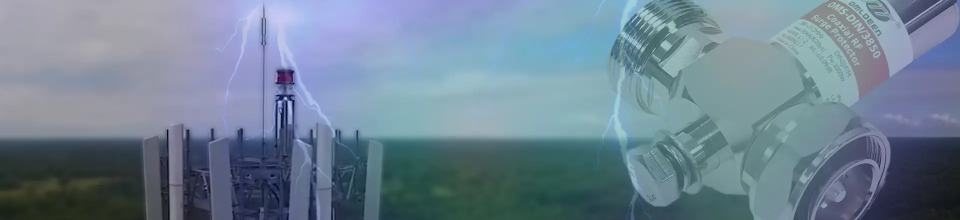


")
 Antenna, Female to Male, 10kA, DC Pass")
")


,DC-Pass")
,DC-Pass")
