 Omrdon Technology
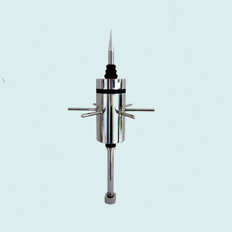
OML-ESE/F3 Ionizing lightning rod, OmniLEDON Ionizing lightning rod
Product Description:
OML-ESE/F3 ionization lightning rod (pre-discharge lightning rod) is based on the principle of traditional lightning rod discharge, the introduction of the “promotion of ionization”, the basic characteristics of preventive lightning rod, so as to achieve an earlier than ordinary lightning rod pilot discharge, expanding the protection radius and improve the safety factor. In lightning conditions, when the lightning downward pilot close to the ground, any conductive surface will produce an upward pilot. In the case of passive lightning rods, the upward pilot is propagated only after a long period of charge recombination. The excitation time of the uplink pilot of an ionized lightning rod is considerably shorter. In the case of high static electric field characteristics before the lightning discharge, OML-ESE/F3 Ion Early Discharge Receiver generates a pulse of controllable amplitude and frequency at the tip of the needle, which causes the lightning rod to generate an upward pilot and propagate it upward to intercept the downward pilot emitted from the thundercloud, thus achieving the purpose of the first discharge. Due to its specially designed ionization process, it is able to generate the upward pilot earlier than other neighboring high points, thus achieving the purpose of the first discharge. The trigger time of the advance value, known as the pre-discharge time △ T. This is the assessment of the pre-discharge type lightning rod (ESE type lightning rod) performance of the main indicators.
For pre-discharge time, it is defined in the NFC 17-102 standard as the difference between the average of the upstream pilot mean start time from an early discharge lightning rod and the average of the upstream pilot mean start time from a simple type lightning rod. This is a test statistic calculated from the results of comparing an ESE lightning rod to a simple lightning rod under the same test conditions in a high voltage laboratory.
Functional Features::
- The fastest preemptive discharge time, i.e., prioritizing the lightning into the ground, the protection radius is greatly increased.
- The lightning fall is more accurate and reduces the probability of the lightning strike point falling on a non-lightning rod body.
- Under the same installation height, the protection radius is several times larger than that of ordinary lightning rods.
- Pure physical structure type lightning rod, no internal electronic devices, no aging, maintenance-free.
- Beautiful appearance, the use of stainless steel materials, can be installed in harsh environments.
- OML-ESE/F3 Ion Lightning Rods are easy to install: light weight, no need to add coaxial shielded cable.
typical application
- Communications base stations
- weather stations
- gas station
- power system
- airfield
- Military systems
Technical Parameters
| Radius of lightning protection of OML-ESE/F3F3 ionized lightning rods of different installation heights for various types of lightning-proof buildings (Rp) | |||||||||
| H=OML-ESE/F3 Height of lightning rod on the horizontal plane of the protected object | |||||||||
| Installation height of OML-ESE/F3 ionizing lightning rod | 2 | 3 | 4 | 5 | 6 | 8 | 10 | 20 | 40 |
| Type I mine protected buildings | 32 | 48 | 65 | 79 | 79 | 79 | 79 | 80 | 77 |
| Type II mine-protected buildings | 40 | 59 | 78 | 97 | 97 | 98 | 99 | 102 | 105 |
| Type III mine protected buildings | 44 | 65 | 86 | 107 | 107 | 108 | 109 | 113 | 118 |
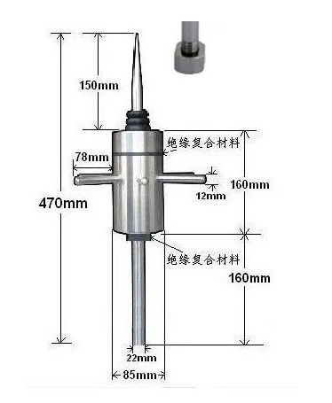
Lightning rod structure of field transformer
Lightning rod installation instructions
1, according to the area of the protected building, height, location of the number of days of lightning and geographic environment correction factor, the nature of the use of the building to determine the category of building lightning protection.
2, with lightning protection category and the area of the building, to determine the selection of one or several IF3 ionized lightning rods.
3. The lead wire (lower conductor) should be electrically connected to the main steel reinforcement of the building, or two or more lead wires (lower conductor) should be made according to the regulations.
4. The lead wires (lower conductors) should be disconnected and insulated on the ground nearby.
5, grounding body, grounding resistance, lightning protection ground network should be in accordance with the requirements of lightning protection standard GB50057-94.


